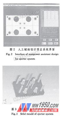
In the module of the artificial auxiliary design ejector system, in order to make the human-machine interface more intuitive, simple but without loss of accuracy, a combination of digital input and graphic performance is adopted. Since the front push plate is one of the parts of the fixed push rod, it is more intuitive to observe the position of each guide hole and judge whether it exceeds the fixed limit, so the front push plate is selected as the substrate for the guide hole position parameter input. In the man-machine interface, the length and width dimensions of the front push plate are drawn into a rectangle according to a certain ratio and presented to the user, and the center position of the rectangle is used as the coordinate origin, and the user calculates the position coordinates of each guide hole based on this. In the form of numbers, the system is input to the system. At the same time, the computer uses the Circle method of the Picture control in VB to draw the circle at the corresponding coordinates to indicate the position and size of the guide hole, and fills the inside of the circle with the background color of the Picture control. Achieve the visual effect of the hole and truly realize the characteristics of "what you see is what you get". Compared with the traditional simple digital input mode, the interface is more friendly and easy to operate. Its interface is shown in Figure 2. The hole spacing interference judgment is performed while drawing the circle, and the magnitude relationship between the center of each circle and the radius is used, that is, when the distance between the centers of the two circles is greater than the sum of the radii of the two circles, no interference occurs between the guide holes, and vice versa. . Only when all the input guide hole spacings do not interfere, the system temporarily stores all the push rod and push plate guide column parameters in the array, and the relevant part model size of the supporting mold base can be generated by calling the SolidWorks program. The corresponding three-dimensional model of the formwork ejection system is shown in Figure 3. 3 Based on the secondary development of SolidWorks mold parts SolidWorks is a product-oriented CAD system developed specifically in the Windows environment. It inherits the excellent interface of Windows, supports Windows DDE mechanism and OLE (Object Linking Embedding), and its design process is fully correlated. , so that the design data in the model file, such as size, comments, file attributes, etc., is related to the drawing. Users can also use the SolidWorks API and secondary development of SolidWorks through development tools that support OLE programming to create a dedicated Solid-Works module that suits the user's needs. In the SolidWorks API, its various functions are encapsulated in SolidWorks objects, and like other VB objects, have their own independent properties and methods. These objects cover all of SolidWorks' data models. By calling these object property settings and methods, users can implement the same functions in SolidWorks as they do in SolidWorks, and can complete part modeling and modification and parts. Feature information extraction (such as feature size setting and extraction, information extraction of features on the face and various geometric and topological information. Since the parts of the standard formwork are roughly the same, they differ only in the number and size of the features. Therefore, for a similarly shaped part of the same type, a parametric design can be adopted, that is, a set of parameters is used to constrain the structural size of the part, so that the parameter corresponds to the control size of the designed part, and when different parameter values ​​are given, it can be generated. New part model. There are basically two ways to parameterize a design: (1) Programming method: All the relationships of the design process are included in the application, and the program is used to sequentially execute the design process. (2) Dimensional driving method: The dimensional dimension of the model is regarded as a variable while keeping the model structure unchanged. Given different size values, a series of similar parts with the same structure and different sizes can be obtained. The system utilizes the size driving method, according to the standard mold frame parameters selected by the user and the part data that has been stored in the array in advance, and uses the program to drive the designed mold formwork part model and assembly model for parametric modeling, and each Sub-modification or reconstruction only needs to call up the corresponding model for size driving. The final assembly solid model of the formwork generated by the system through Solid Works As shown in Figure 4. Previous page next page Oem Service,Obm Service,Stamping Parts Simple Shower Room Co., Ltd. , http://www.chinaatvpart.com