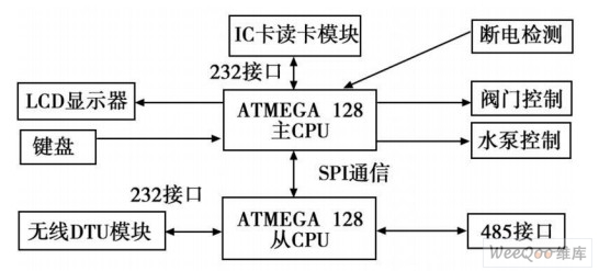
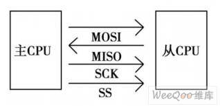
Abstract: A sewage discharge monitoring system for sewage enterprises in sewage treatment plants was designed. It mainly monitors the on-site data such as real-time flow rate and flow rate of discharged sewage. It adopts 485 communication, wireless DTU transmission, Internet access and other communication methods to solve the problem of data transmission in the remote field environment, realizing the real-time uploading and sewage control field control function of sewage discharge field data. 0 Preface In recent years, the urban sewage treatment industry has entered a period of rapid development. Sewage discharge enterprises will discharge sewage into the sewage treatment plant for centralized sewage treatment, and the sewage disposal enterprises will pay according to the amount of sewage discharged. The traditional sewage discharge is mainly copied by the on-site flowmeter of the sewage disposal enterprise. However, this method is time-consuming and laborious because the sewage disposal enterprises are relatively scattered. Therefore, a centralized monitoring system for sewage discharge enterprises has been designed. Through the system to collect the real-time flow, flow rate, motor status and other field data of sewage discharge enterprises, centralized transmission to the sewage The monitoring center of the plant controls the on-site sewage discharge in real time through the monitoring center. 1 Overview of centralized sewage discharge monitoring system The block diagram of the sewage treatment centralized monitoring system is shown in Figure 1: Figure 1 Block diagram of centralized sewage monitoring system The centralized monitoring system consists of three layers: the top layer, the middle layer, and the bottom layer. The top layer is the upper computer of the monitoring center, responsible for the system monitoring task, through the Internet access and communication between the wireless data transceiver (DTU), where you can see the real-time situation of the underlying parts, and some of the underlying Partial control. The middle layer is the sewage discharge monitoring terminal, which is responsible for data processing and transmission, and controls the underlying actuators and collects the underlying field data. It is both a data collector for each field object and part of these data processing and centralized transmission. The bottom layer is a field data acquisition and control unit, which can process the data coming from the host computer, and can enable the peripheral circuit to perform corresponding actions. At the same time, it can also collect data from the analog quantity in the surrounding environment and send it to the monitoring terminal. 2 Monitoring terminal system design 2.1 System function requirements According to the requirements of the monitoring system, the monitoring terminal must have the following functions: (1) It is able to collect data of sewage flow meter, including accumulated flow, real-time flow, flow rate and other parameters. (2) It is possible to control whether the enterprise can discharge sewage according to the payment situation of the sewage discharge enterprise. (3) The operation of the system can be controlled remotely. (4) The system can be controlled locally in the case of poor network or other special circumstances. (5) The system must be authorized to proceed. (6) In the case of power failure, the system must be able to run the valve closing command, and the system is closed after the valve is closed. The above requirements of the functional system use two ATMEGA128 as the processor, which solves the problem of insufficient UART of ATMEGA128 itself, and reduces the workload of the main CPU, so that the system can run stably. 2.2 System structure block diagram According to the above requirements. The structure diagram of the monitoring terminal system is shown in Figure 2. Figure 2 Monitoring terminal system structure The system uses two ATMEGA128 as the processor, and constitutes master-slave communication through SPI. The main CPU is responsible for human-computer interaction, non-contact IC card reading, power-off detection, and control of the pump valve. The slave is responsible for communication with the flow meter and for the transmission of data to the monitoring center via the wireless data transceiver (DTU) and the transmission of the monitoring command. 2.3 System SPI communication function ATmegal28SPI features the following: full-duplex, 3-wire synchronous data transmission. The master or slave operates, LsB is sent first or the MSB is sent first. 7 programmable bit rates, end of transmission interrupt, write collision flag detection. Can wake up from idle mode. It has a two-speed mode (CK/2) as a host. Figure 3 SPI communication The SPI communication system includes two shift registers and a host clock generator. Pull the ss pin of the desired slave down. The host initiates a communication process. The master and slave put the data that needs to be sent into the corresponding shift register. The master generates a clock pulse on the SCK pin to exchange data. The host's data is removed from the host MOSI. Move in from the slave's MOSI; the slave's data is removed from the slave's MISO. Move in from the host's MISO. The master synchronizes with the slave by pulling the SS of the slave. 3 monitoring terminal system software function realization The system software is divided into the main CPU part and the slave CPU part. The main CPU part of the main functions are as follows: (1) Pump valve control: After power-on reset, the system obtains the control status of the pump and valve from the monitoring center through SPI communication without keyboard operation, and closes or opens correctly. (2) Power failure detection: The system periodically detects whether the external power supply is powered off. If the power is turned off, to prevent the human power from being shut off, the valve and the water pump are shut off immediately. In order to prevent short-circuit trips and power failures, the system performs a delayed power-off. (3) Calculate whether the accumulated current displacement exceeds the allowable displacement. If it exceeds, the valve and pump can be closed according to the preset setting, and the alarm information can also be sent to the monitoring center. (4) Real-time data display: When no human-machine operation is performed, the LCD display displays the measurement data such as real-time water volume and flow rate, and the status of the devices involved in the system. Real-time reflection, at a glance, easy for companies to view. (5) Local authorization operation: In order to prevent the occurrence of network problems, the drainage enterprise will insert the IC card into the local monitoring terminal after recharging, on the one hand, the local storage of the allowable displacement or the pre-stored amount, and on the other hand, the IC card can be passed under special circumstances. Authorize the system to control the operation of valves and pumps. The system adopts a non-contact IC card reading and writing module. After detecting the card swiping, the module sends the card number command to the host. After receiving the command, the host must send the card reading command, write card command, plus or minus command within 300 milliseconds. Any one of the commands, if the module does not receive one of the above commands within 300 milliseconds, the module will automatically close the card and perform the next round of card detection. If one of the above commands is received within 300 milliseconds, the module will process according to the received command, and the command can be sent continuously as long as the two commands do not exceed 300 milliseconds. The module will automatically close the card and perform the next round of card detection beyond 300 milliseconds. Read and write operations to the card sent after the card is closed will fail. The main functions from the CPU part are as follows: (1) Flowmeter data acquisition: collects flow data of one or more drainage points of the drainage enterprise through the 485 bus. (2) Wireless data communication: The system transmits the collected traffic data to the monitoring center in real time through the wireless data transmission device (DTU) and accepts the instructions of the monitoring center. The DTU is based on the GPRS network. The DTU is relatively simple to use because it encapsulates the PPP dialup protocol and the TCP/IP protocol stack. Moreover, DTU designs the serial port data into a "transparent conversion" mode, which means that the DTU can convert the original data on the serial port into TCP/IP data packets for transmission without changing the original data communication content. Therefore, the DTU can be connected to various user equipments that use serial communication, and no modification to the user equipment is required. Before the actual use, configure the DTU, set the serial communication parameters, set the parameters of the remote access server and other communication parameters. After the setting is completed, it can be treated as a serial device only in the system. 4 system anti-jamming design Since the monitoring terminal system is operated at the sewage disposal enterprise site, it is easy to be disturbed by high-power electrical equipment, which causes problems such as system operation errors or crashes. Therefore, the system is designed to take hardware anti-interference and software anti-interference measures especially for on-site interference. The specific measures are as follows: (1) Firstly, the hardware design fully considers the anti-interference of the power supply and the circuit. The smoothing reactor is designed at the input end of the power supply 220 V. The DC output of the power supply adopts the electronic filtering technology to minimize the interference from the power supply. (2) Secondly, consider the grounding of the system. In addition to following the grounding principle of digital ground and analog ground in circuit design, the method of grounding the casing for the components that are susceptible to interference such as LCD liquid crystal display, and the method of grounding the whole casing of the system greatly reduces the interference of the industrial site. (3) Finally, a variety of anti-interference design techniques are used in software design. The system adopts methods such as state detection and cycle reset for components that are susceptible to interference, thereby avoiding system abnormalities caused by external device errors and the like. When high-power devices such as pumps are switched, sleep, delay, etc. are used to avoid interference from these known interference sources. In addition, a perfect data frame communication protocol is adopted in data communication, and the CRC check function is provided, which greatly reduces errors in communication and improves communication reliability. 5 Conclusion The design and application of centralized sewage discharge monitoring system provides a reliable means for efficient real-time management of wastewater enterprises. On the one hand, it saves the labor meter reading cost of sewage treatment plants, and on the other hand, it greatly reduces the phenomenon of sewage disposal by sewage companies. Stable operation for nearly a year has achieved good results.
This type belongs to closed type. Has superior seal type and constructability, make with different colour. Maily used in temporary signal board, work site and advertising board, having three years`s weathering resistance. It is suitable for AL board and steel board.In the daytime with its bright colors play a clear role in the warning, at night or lack of light in the case of its bright reflective effect can effectively enhance people's ability to identify, see the target, causing alert, so as to avoid accidents, reduce Personnel casualties, reduce economic losses, become an indispensable road safety safety guards, has a clear social benefits.
Commercial Grade Reflective Sheeting Commercial Grade Reflective Sheeting,Pet Type Stripe Warning Tape,Pet Type Commercial Grade Reflective Sheeting,Acrylic Type Commercial Grade Reflective Sheeting Daoming Optics & Chemical Co., Ltd , http://www.dmreflective.com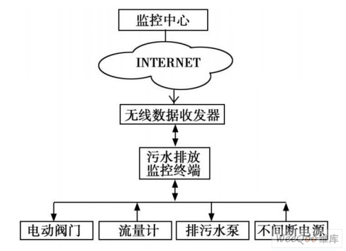
Source: The wind is coming in the rain
Design and implementation of sewage centralized emission monitoring terminal
0 times
Window._bd_share_config = { "common": { "bdSnsKey": {}, "bdText": "", "bdMini": "2", "bdMiniList": false, "bdPic": "", "bdStyle": " 0", "bdSize": "24" }, "share": {}, "image": { "viewList": ["qzone", "tsina", "tqq", "renren", "weixin"], "viewText": "Share to:", "viewSize": "16" }, "selectShare": { "bdContainerClass": null, "bdSelectMiniList": ["qzone", "tsina", "tqq", "renren" , "weixin"] } }; with (document) 0[(getElementsByTagName('head')[0] || body).appendChild(createElement('script')).src = 'http://bdimg.share. Baidu.com/static/api/js/share.js?v=89860593.js?cdnversion=' + ~(-new Date() / 36e5)];