The core component of the fire pump is the impeller, and the design of the impeller is related to the working performance and service life of the whole machine. However, the impeller hydraulic design requires a lot of complicated calculations, comparisons and repeated modifications, with a large workload and a long design cycle. Therefore, actively developing and researching hydraulic CAD (Computer Aided Design) system suitable for fire pump can not only reduce the design workload, improve the development speed and quality, but also have important theoretical significance and practical application value for promoting the design of fire pump impeller. Second, the development tool selection At present, in the CAD software market, there are many CAD software products available for CAD system support environment and development environment and tools [1], high-end I-DEAS, Pro/E, UG, etc.; Mid-range Solid Works , MDT, etc.; low-grade AutoCAD. Among them, Autodesk's AutoCAD can be regarded as one of the most successful and influential computer-aided design software. It has the advantages of reasonable price, convenient use, open architecture and good versatility. It is well received by engineers and technicians and has been widely used at home and abroad. AutoCAD has now reached AutoCAD 2004 from its original version, and its secondary development tools are constantly being updated and increased, giving users more freedom to choose. Therefore, how to choose the right development tools becomes a problem that needs to be solved. Due to the development of science and technology and the improvement of software development level, there are fewer and fewer users using Auto LISP and ADS development tools. Currently, there are four development tools: ARX, VB, VBA and Visual LISP. The comparison of development tools is shown in Table 1). Table 1 Comparison of four development tools Among the above four development tools, since ARX is based on the Visual C++ platform, like VB and VBA, they all come with a large number of visual programming controls, so that the design of human-computer interaction interface is more convenient and faster during software development. So that the developed software is more personalized, and Visual LISP is lacking in this regard. Especially in software development, if you need to interface with the database, ARX, VB and VBA tools have dedicated database controls that can be directly selected, which can save a lot of tedious work. Although powerful, ARX runs fast, but the language is complex and difficult to master. If the program does not properly handle a detail in Windows programming, the application, the development environment, and the entire Windows are likely to be embarrassing. VB/VBA, although running at a relatively slow speed, has a simple syntax and a powerful function for developing a graphical user interface. Many graphics algorithms are very efficient, even in languages ​​such as VB/VBA, which are relatively slow. Moreover, in most cases, the speed of VB/VBA is fast enough. In terms of language structure, VBA[2] is a subset of VB, and their grammatical structure is the same. The obvious difference in appearance is that all functions of VBA, although similar to VB, are not as good as VB. The real essential difference between them is that VB is a stand-alone development tool that does not need to be attached to any Other application. It has its own completely independent working environment and compile and link system. VBA is not, it does not have its own independent working environment, it must be attached to a main application, such as Office, AutoCAD, etc., leaving the main application VBA will no longer exist, which limits its application in development, but also the author The main reason for not choosing VBA in the end. Therefore, Visual Basic 6.0 was selected to develop the hydraulic pump CAD software of the fire pump, and the function of VB itself was fully utilized to perfect the relatively weak links of AutoCAD except graphics processing, so as to realize the complementary advantages between programs. Third, the system interface and operational requirements 3.1, system operation requirements In order to make the system run well on the computer, the computer system should have the following hardware and software configuration: 3.1.1, hardware configuration (1) Pentium 133 or higher CPU; 3.1.2, software configuration (1) Windows 9X or Windows NT 4.0 and above; 3.2. System Interface As shown in Figure 1, the system interface consists of a title bar, a menu bar, a toolbar, a software running area, and a status bar. Figure 1 system interface Fourth, the system design features and design techniques 4.1, design features (1) Friendly user interface, easy to operate. The operation mode adopts man-machine dialogue mode, which runs through interactive design ideas throughout the design process, and uses dialog boxes and menus to convey and process information, so that designers can better grasp the design process. 4.2, design technology 4.2.1, interactive technology It should be pointed out that: CAD is not entirely design automation, CAD puts people's dominance and creativity at the forefront, while giving full play to the strengths of computers, so that the two can be organically combined. Therefore, in order to provide designers with space for design experience, the system adopts some human-computer interaction methods to establish channels for human-computer information exchange in the form of dialog boxes and menus. 4.2.2 Modular Technology Modular technology is a commonly used method for designing CAD systems. Divide the system into individual functional modules, then design the sub-modules, and finally synthesize a system, which is beneficial to the development, debugging and maintenance of the system, and also to the system update. 4.2.3, ActiveX Automation Interface Technology The programming interface provided by ActiveX Automation makes it easy for users to customize AutoCAD using various ActiveX client programming languages ​​(such as VB, Delphi, etc.). It can be used for applications in Windows environments to manipulate objects in AutoCAD, such as creating views in AntoCAD, specifying and extracting extended data, outputting graphics to peripherals, adding professional objects to AutoCAD, and more. Using VB, Delphi and other programming languages, you can seamlessly connect applications on the Windows platform, so that all programs can be integrated into a unified operating environment. 4.2.4 Database Technology The database [3] mainly stores design calculations, drawings and various standard data. The purpose of establishing such a database is to reduce or even eliminate the need to manually access the design data in computer-aided design; at the same time, the intermediate data in the design is stored in the database to reduce the number of data output and input. Five, functional module division and flow chart 5.1. Functional module division of hydraulic design module The hydraulic design module of the fire pump CAD system consists of four sub-modules: (1) Basic parameter determination module: including the basic parameter determination of the pump and the determination of the basic parameters of the impeller; The relationship between the modules is shown in Figure 2. Figure 2 Functional modules for hydraulic design 5.2, hydraulic design flow chart The hydraulic design flow chart of the impeller is shown in Figure 3. Sixth, the conclusion The development of the hydraulic pump hydraulic CAD system has great practical significance, and achieves the effects of accurate calculation and drawing, short design cycle, simple and intuitive, and achieves the intended purpose. The mature CFD software is used for flow field analysis and performance prediction. Based on this, the hydraulic design method is further improved and revised. This is also one of the research priorities and directions in the future. Engineered Wood Flooring,Wood Flooring,Wood Floor Hongda Anxin Decorative Material Co., Ltd. , http://www.hb-flooring.com I. Introduction 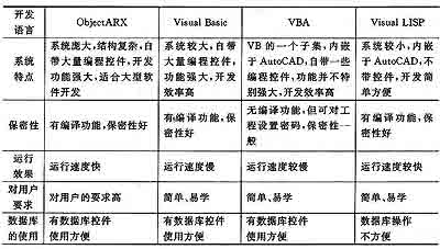
(2) Basic memory above 32MB (recommended 64MB or more);
(3) Displaying 16 or more enhanced Colors;
(4) More than 300MB hard disk space.
(2) AutoCAD2000 or above;
(3) Access97 or above. 
(2) The amount of data is large and the relationship is complicated. In the hydraulic design process, there are many parameters involved. The design data of the previous design is often used in subsequent designs. For example, the basic parameters of the impeller determined in the previous drawing are required to draw the axial projection, and the axial surface is required to draw the axial section. Specific data of the projection map, etc.
(3) A large amount of graphic information processing. There are many graphics that need to be processed during real-time operation. Both the middle bitmap (.bmp) and the final AutoCAD graphics (.dwg) output.
(4) The program design fully considers the different habits of the user, and provides operation prompts and guides in multiple places: the operation prompt can help the user to reduce the operation error; the operation guide allows the user to self-pass. Help file users can expand themselves and the system has good maintainability. While considering professionalism, try to improve the versatility and practicability of the program.
(2) Axial flow channel design module;
(3) Leaf type drawing module;
(4) Wood mold drawing module.