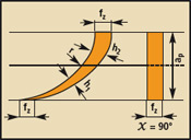
Radial chip thinning is an effect produced when the radial cutting width (WOC) ae used for milling is less than 25% of the diameter of the milling cutter. As the radial cutting width decreases, the chip thickness based on the design feed per tooth fz will also become thinner, resulting in a reduction in the actual feed per tooth fz, while the reduction in fz will cause the tool and workpiece. The surface is scratched and cannot be cut into the workpiece, so it is necessary to increase the feed amount fz per tooth when the radial depth of cut is reduced. High feed milling with thin radial chip thickness (see Figure 1) reduces machining time and tool life. Figure 1 High feed roughing of thinned chips Tool lead angle change The tool's lead angle is the most important factor in achieving chip reduction. When a flat tool main angle χ is used, the tool starts to cut at a 90° lead angle. As the cutting progresses, the main angle decreases and the chip thickness h decreases. When machining a particular type of workpiece material, different cutting parameters are required to achieve optimum chip thickness. The feed per tooth that needs to be input when programming the CNC machining program can be calculated by the following formula: fz=h/sink. The value of h given for a certain type of workpiece material has a range of values, with the smaller value being the chip thickness value at the start of the cut. When milling aluminum or non-ferrous alloys on machining centers with a machine power of 50 hp, the recommended chip thickness range is h=0.002′′-0.003′′ (0.051-0.076 mm); when machining stainless steel, aluminum alloys and heat-resistant superalloys The recommended chip thickness range is h = 0.003" - 0.006" (0.076 - 0.152 mm); when machining steel, cast iron and ductile iron, the recommended chip thickness range is h = 0.006" - 0.010" (0.152 - 0.254 mm). If a chip thickness greater than the recommended value is used, there is a risk of blade overload and chipping of the cutting edge. Regardless of the tool's main yaw angle of 90°, 60°, 45°, 30° or less, the chip thickness will remain the same, except for the circular inserts used in round or button mills (see Figure 2). Since the top of the round insert has no geometric edge and the chamfer is extremely small, the cutting edge has the highest strength. Ap—cutting depth b—chip length fz—feed per tooth h—chip thickness r—radius k—main yaw angle Figure 2 Blade cutting cross-section shape with different lead angles (90°-30°) Round blade) Unlike straight edge inserts, the chip thickness cut by the round insert will increase as the depth of cut increases. Therefore, the average chip thickness hm can be used to indicate the cutting thickness of the circular blade. The hm value is determined based on the chip thickness at the radial joint of the circular blade through the tool diameter to the workpiece. For different types of workpiece materials, the typical range of hm values ​​is the same as the range of h values ​​above. A circular insert (RDMT 2006) was compared to a 90° insert (ADMT 1606). If the two inserts are cut with the same depth of cut and feed per tooth, the amount of chips they cut is exactly the same. However, if the cutting depth is 1/2 of the inscribed circle (IC) of the circular insert, the chip thickness of the round insert will be reduced by 30% because the cutting edge of the circular insert that is radially engaged with the workpiece is longer ( See Figure 3). In other words, if the circular blade and the 90° blade each cut the same amount of chips, and the cutting blade produces a chip length of about 50% longer than the 90° blade, the chip thickness cut by the circular blade is inevitably greatly reduced. At this time, if the feed rate remains the same and the cutting depth is reduced to be equal to 25% of the inscribed circle of the button milling cutter, the chip thickness cut by the button milling cutter will be reduced by 50% when the amount of cutting chips is equal. . In order to achieve productivity by thinning the chip thickness, the maximum depth of cut selected should be 20%-25% of the inscribed circle of the circular insert. Ap—cutting depth fz—feed per tooth h—chip thickness r—radius k—lead yaw angle Figure 3 Circular insert (RDMT2006) and straight edge insert (comparison of chip thickness of ADMT1606) Apmax—maximum depth of cut ap—cutting depth k—main lead angle Figure 4 In copy milling, when the depth of cut becomes shallow, the lead angle is flattened Increase in feed rate Since the chip thickness is thinned as the depth of cut becomes shallow, in order to obtain a high level of processing productivity, it is necessary to compensate for a small depth of cut by increasing the feed rate. Whether using a round insert or a small lead angle milling cutter, the chip thinning effect can be used to achieve high feed rate milling, because as the cutting depth of the circular insert becomes shallower, the lead angle is also flattened. (See Figure 4). Therefore, when determining the feed per tooth of the input CNC machining program, the variable average chip thickness hm and the main declination kχ are substituted into the calculation formula fz=hm/sink, and the feed rate can be greatly improved (can be doubled) ). To determine the effective lead angle of the button cutter, the following formula can be used: tank=ap/(ICeff/2)k=effective lead angle (where ICeff is the effective inscribed circle). It should be noted that when the plunging angle is 90°, the feed per tooth of the input machining program is equal to the chip thickness. If the lead angle is reduced, the amount of chips will remain the same, but the length of the joint between the cutting edge of the tool and the workpiece will increase, and the resulting chip thickness will be less than the programmed value, but the chips will become longer. In the case where the depth of cut is smaller than the radius of the circular blade, in order to increase the chip thickness to the programmed value, it is necessary to increase the programmed value of the tool feed rate. Therefore, although the cutting blades produced by the round insert have the same chip thickness as the straight edge insert with a 90° lead angle, the feed rate of the button cutter for cutting the workpiece material is much higher. Of course, in order to remove a certain amount of workpiece material, there is also a certain requirement for the power of the machine tool. If the feed rate of the tool is doubled, the power of the machine tool also needs to be doubled. In roughing, a milling cutter with a 90° lead angle is the most unfavorable for improving machining productivity, but this cutter is more suitable for machining a 90° shoulder because it does not require a secondary pass for root cleaning. In order to reduce the types of tools used, some workshops mainly use 90° straight edge milling cutters for milling. In other cases, such a milling cutter is not required. In the case where the cutting depth remains the same, the smaller the circular blade, the lower the processing efficiency. This is because the main blade of the small blade has a larger main angle, and it is substituted into the setting formula of the feed per tooth. The rate of arrival is also small. In addition, when the cutting depth of the circular blade is increased, the processing efficiency is also lowered. Therefore, when a button cutter is milled with a cutting depth equal to 50% (IC/2) of its inscribed circle (the maximum depth of cut possible), the chip thickness it cuts is set by the machining program. The feed per tooth is exactly equal and the machining efficiency is the same as a straight edge milling cutter with a 45° lead angle. However, if the round insert of the button cutter has 4 cutting edges, its cost-effectiveness is higher than that of a 45° double-sided insert because the 45° double-sided insert has 8 cutting edges ( The button blade has a cutting edge on only one side, while the 45° double-sided blade has a cutting edge on both sides. One of the limiting factors in using the round insert to achieve the chip thinning effect is the depth of cut. The largest standard round insert diameter is approximately 0.800" (20mm), so the maximum depth of cut for high speed milling is 0.200" (5mm) - or 0.250" (6.35mm) is permitted. Although the 45° straight edge milling cutter can be more Large depth of cut for milling, but the button milling cutter can use a secondary pass (if needed) for roughing machining to achieve higher cutting efficiency than other tools. When machining with chip reduction technology, if the generated chips are too thin, the surface of the tool and the workpiece will be scratched. For example, when cutting with a large chamfering blade at an extremely low feed rate per tooth, the chips are difficult to form normally and flow smoothly. Change in cutting force direction When the tool's main declination is flattened and the chips are thinned, the direction of the cutting force also changes. For example, when cutting with a 45° lead angle cutter, the axial cutting force is equal to the radial cutting force. Since the radial cutting force causes tool deflection and chattering; and the axial cutting force acts on the spindle of the machine tool, the machining process is less affected by destructive vibration. Therefore, the cutting force generated by using a tool having a small main off angle is mainly an axial cutting force, which is advantageous for maintaining the stability of the machining process. In summary, for rough milling with the goal of cutting the most workpiece material in the shortest time, by reducing the tool lead angle and using a smaller depth of cut, the chip thinning effect can be achieved and the tool can be greatly improved. The feed rate, which significantly improves the efficiency of rough milling. Face Powder Puff,Foundation Puff,Mini Powder Puff Liya Beauty Accessories Co., Ltd. , http://www.chinapowderpuff.com


High feed rough milling technology for thinning chips (figure)
The goal of rough milling is to remove as much metal material as possible from the workpiece in the shortest amount of time. Although the material removal rate depends mainly on the effective power (horsepower) of the machine tool, by using the method of radially thinning the chip thickness, productivity can be maximized and maintained even on a low-power machine. The cutting conditions required for processing.