Nowadays, the application range of DC electric energy meter is rapidly expanding, including not only DC energy measurement in the fields of trolleybus, tram, subway vehicle, electric vehicle and photovoltaic power generation, but also suitable for modern supply and distribution of industrial and mining enterprises, civil buildings and building automation. DC system. In other words, with the continuous expansion of the application field of DC electric energy meters, the demand for accurate metering is also increasing. However, after searching and searching at home and abroad, it is impossible to obtain an electronic DC electric energy meter inspection device. Therefore, in this case, Here, a DC electric energy meter inspection device is designed. LabVIEW is a virtual instrument development platform software that is programmed in a graphical programming language. It is simple and intuitive, greatly saving program development time. It is powerful and flexible, and can be widely used in automatic measurement systems, industrial process automation and laboratory simulation. The DC electric energy meter verification device based on LabVIEW software has a friendly interface and intuitive display. The virtual instrument designed according to the physical model displays the collected voltage and current values ​​in real time, and has good visualization effect, convenient debugging and strong versatility. 1 Design and implementation of DC electric energy meter inspection device The PC automatically controls the entire DC energy meter verification process according to the set inspection conditions (including the test time, voltage and current reference values, etc.), and communicates with the tested energy meter using CAN or RS-485 bus to obtain the checked energy meter. Energy metering. At the beginning of the test, the PC controls the voltage source and the current source to output a preset signal, and the metering device and the metered meter are simultaneously measured. During the inspection process, the PC collects the corresponding voltage and current signal values, and uses the integral method to calculate the electrical energy. The result is used as the energy measurement reference. The user interface displays the power reference value, and at the same time, obtains and displays the measured result of the checked electric energy meter according to the set communication mode, and calculates and gives the measurement error of the checked electric energy meter. The output of the voltage source and current source can be remotely adjusted by the PC through the control module. The PC uses the multi-channel analog signal output function on the control module to convert the set power target output value into a corresponding analog control signal, which is connected with the signal of the voltage source and the analog control interface of the current source, thereby realizing the PC pair. Remote control of two power supplies. The overall structure of the designed system is shown in Figure 1. 2 Principle of reference energy measurement The reference energy measurement in the DC energy meter test device is calculated by the integral method, and the method has strong anti-interference ability. This is because the inspection of DC energy meters must take into account the characteristics of the relevant working environment: 3 hardware design Figure 1 shows the overall structure of the DC energy meter test method and device. The various components of the system and their functions are as follows: Runway Deicer,Organic Salt,Airport Runway Deicer Weifang Meltway Co., Ltd. , http://www.wfsnowmelting.com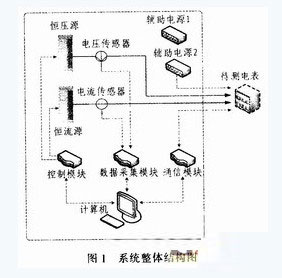
1) DC pulsation of energy It is very likely that the AC component will be superimposed on the supply voltage, and the load current is likely to change frequently;
2) The fluctuation range of the network voltage is large, and the voltage fluctuation range of the DC power supply network reaches or exceeds ±20%;
3) A large number of high-order harmonic components of the network voltage. Not only the network voltage itself is pulsating, but some electrical equipment also generates a large number of harmonics on the network.
In summary, the reference energy metering is calculated by the integral method, that is, the calculation method of energy consumption within a certain period of time (t1~t2) is as follows:
In the formula, u(t) and i(t) are the operating voltage (V) and current (A) at time t in the period from t1 to t2, respectively, and W is the electric energy (kWh) consumed during the period from t1 to t2. . The total energy consumption value is obtained by accumulating the energy consumption in each time period.
1) Constant voltage source According to the working voltage range of the tested DC energy meter, an adjustable DC working voltage is provided;
2) Constant current source According to the working current range of the tested DC energy meter, an adjustable DC load current is provided;
3) The voltage sensor measures the DC voltage, and the output isolated electrical signal is sent to the data acquisition module. The CV3-1000 type of the Swiss LEM company is selected, the rated input voltage is 700 V, and the measurable range is 0~±1 000 V. The measurement accuracy is less than ± 0.2%, can measure DC, AC, pulse current signals, signal frequency range 0 ~ 500 kHz;
4) The current sensor measures the DC current, and the output isolated electrical signal is sent to the data acquisition module. The ITB 300-SCT5-T type of the Swiss LEM company is selected, the rated input current is 300 A, the measurable range is ±450 A, and the measurement accuracy is less than ±0. .05%, can measure DC, AC, pulse current signals, signal frequency range is 0 ~ 100 kHz;
5) Data acquisition module Convert the output analog signals of the voltage sensor and the current sensor into digital signals for use by the PC, select Advantech's PCI1716L, and the sampling rate reaches 250 thousand times per second;
6) The control module is customized according to the design requirements, receives computer control commands, and controls the output of the constant voltage source and the constant current source;
7) Communication module Communicate with the tested electric energy meter to complete reading and control. You can use Zhou Ligong's USBCANl CAN communication module or JaRa2206 USB/RS485 converter.
8) PC automatically generates inspection report; graphically displays measurement results; stores measurement results, establishes database; if equipped with printer, can print inspection results.